
Assembly of the Focke-Wulf 190D-9, Eduard 1:48
1. INTRODUCTION
My model is going to represent Focke-Wulf 190D-9, W. Nr. 500570, “the Blue 12”, from 8./JG 6. This is the plane in which, on 8 May 1945, an unknown pilot surrendered to the Americans at Furth-Atzenhof Airport so as not to fall into the hands of the Russians. The pilot was immediately released. The plane was his, and his identity has remained a mystery to this day. This is probably the most frequently seen photograph of the plane:

The plane was made at the Mimetall Erfurt factory sometime in January or February 1945. During its short operational existence, “the Blue 12” was damaged several times and maintenance teams performed whole series of repairs in order to keep it operational. At the time of the surrender, the plane immediately attracted considerable attention and was photographed a lot. To date, the authors of the book FW190D, Part II, did the best job of analyzing all the available photographs in detail. In the making of this model, especially the paintjob, I drew mostly from this book.

I am going to build a model of the plane in flight, with the imitation of a spinning propeller and, of course, a pilot in the cockpit. I prefer WWII fighters in flight, as most of them lose their usual elegance and aggressiveness. Granted, the Fw-190 doesn’t look bad on wheels, but is a real German “bastard” in flight, with its own sort of elegance.
At the time of the surrender, “the Blue 12” did not carry machine guns in its nose. I will install them anyway, as my model will represent this plane in combat flight, e.g. at the end of April or the beginning of May 1945.
2. TEST CONSTRUCTION
Since the construction of Eduard’s Focke Wulfs is known to cause fitting problems – a few years ago, I myself ran into some issues building my A-8 – I was particularly meticulous this time around. I prepared and treated all the necessary parts: the fuselage, the wing, the cockpit, the front firewall, all cooler parts, the upper engine cowlings, the windshield, the canopy, etc.


Even when measuring the two halves of the fuselage, we can see that they do not fit entirely. The most important thing is to straighten the panel lines of both halves of the fuselage right before and after the cockpit. This will ensure that the cockpit is installed correctly, and the windshield and the canopy will fit nicely.


When we attach the wing, the gap where the wing and the fuselage join together is too big, especially on the right side. Of course, part “X26” which, among other things, keeps the lower part of the wings at the proper angle is not yet installed,

but even once it’s installed, the gaps on both sides will still be there.

The right side is more problematic, as the cannon bay cover is not a perfect fit because of the space between the opening in the wing and the opening in the fuselage. If we straighten the wing on the right side, the alignment on the left side is disturbed, and the situation at the bottom is even worse.

There is definitely something wrong with the right half of the fuselage or the right wing (the cannon bay is displaced). I decided to solve the problem of the cannon bay cover with some plastic, puttying and polishing after I glue the fuselage and the wing together.
As my model will represent a plane in flight, the undercarriage legs are going to be in the undercarriage bay and the tailwheel is going to be retracting.
The undercarriage bay openings in the wing are of the appropriate shape but the skin on the undercarriage legs needs some more plastic.


I deepened and widened the tailwheel undercarriage bay a little bit.

3. RIVETING
There are a few rivets on the model, but not much. Kagero’s “Top Drawings” contain excellent designs for the Fw 190-D with scales of 1:72, 1:48 and 1:32. In addition to designs, the publication also contains color schemes for certain planes, including the color scheme for “the Blue 12” which, however, is not completely accurate. It also includes decals for the planes displayed.


As a guide for riveting, I used two or three layers of Scotch tape, cut into 4–5mm-wide strips.
I used a 0.3-mm dentist drill to enlarge the screws on the model. After riveting, I polished the surface with a fine abrasive paper and brushed it with a toothbrush.


Next, I quickly applied a thin layer of liquid model glue on all riveted lines. The liquid glue makes the edges of the rivets a little softer and the holes a little smaller. I used the same technique on engraved lines. Then I degreased all riveted or engraved parts and cleaned them with toothpaste and a toothbrush.
4. THE PILOT FIGURE AND THE COCKPIT
I used the CMK pilot figure for the Me-109. Although the moldings were quite detailed, I decided to polish everything and make it from scratch. One important feature of Focke-Wulf pilots was that they carried parachutes on their backs so they would lean forward a bit in the cockpit.


German fighter pilots wore distinct helmets and goggles.

The following image shows all the equipment worn by the pilots.

I remolded the helmet, made goggles, a parachute and straps.


I also made a compass that the pilots would wear on their right arm or have it hanging from their life jackets (the RLM 66 Eduard color on the etched parts is wrong).


I made the goggles from a thin copper wire. The glasses are made from a white glue for transparent parts and colored with the Tamiya X-26 color.

The parachute straps are made from colored paper, and the seatbelts and all the buckles are from HGW.


The Fw-190 seatbelts should be fastened to the back wall behind the backrest, and not to the board behind the seat like with the Me-109.


5. CONSTRUCTION OF THE FUSELAGE
First, I glued the cockpit (X9) to the right side of the fuselage and fixed it in the appropriate position by putting on the left side of the fuselage and waiting for the glue to dry. I repeated the process with the firewall (parts X5, X38, X46). I didn’t install the next wall W1 because the engine will be closed, and the fit wasn’t quite right. I also didn’t install the back wheel and the machine guns (W12, W20).


Eduard forgot about the guard above the right-hand exhaust outlets. I made it from the metal of etched parts.


On the tip of the rudder, the Fw 190 had a ring for the antenna. I made it from one of the buckles in the HGW belt set 1:32.


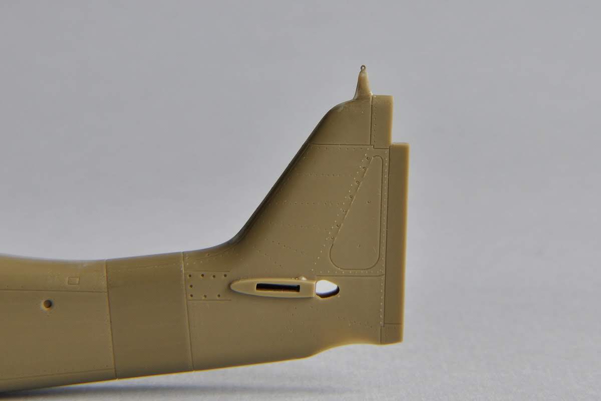

I glued injection needles to the Y22 part under the R8 machine gun cover. I will only install the muzzles after the model is painted.


I made a side pane sprinkler on the windshield. It’s made from a copper wire and tinfoil.


6. CONSTRUCTION OF THE WING
First, I made a mount for the gun tubes from 1.2-mm injection needles. The gun tubes are made from a 0.7-mm injection needle.

When X26 is already glued to the bottom wing, the upper halves of the wing can’t be installed. The upper halves of the wing have a sort of extension (red arrow) that hits against X26 upon installation on the bottom half. This part of the extension can be cut off if it’s in the way (green arrow). I cut all of it off.

I glued plugs on the chassis skin, to which I installed the wheels. I also cut out an opening for the stand.


I made a Pitot tube from 0.6-mm and 0.3-mm injection needles.


I also puttied the skin on the wings for external guns. Some prototypes of the serial Fw 190D had them and some didn’t.

7. JOINING THE FUSELAGE AND THE WING
Joining the fuselage and the wing, I again ran into a problem because of the X26 part. The part where the front wall of the cannon bay was supposed to fit was too thick.

This part of X26 needs to be narrowed.

When the fuselage and the wing are glued together, we have quite some puttying to do, especially on the bottom part.


The front skin where the fuselage and the wing join remains puttied because it’s from one piece (red arrow). But a small skin needs to be engraved (green arrow).

I glued a reinforcement plate, which I made from the metal of etched parts, to the back part of the wing.

The engraving of the back edge of the engine cowling on the bottom is quite complex, as its line runs upwards to the opening of the exhaust outlet. Minor adjustments will need to be made after the model is painted with a primer to make it more visible.


I also engraved a correction on the left engine cowling that the real plane had; more details are provided in the chapter about painting.

I also solved the problems with the right wing. These, too, will require some additional minor adjustments.


7. STAND
The stand is made from transparent plexiglass. I sanded the top of the stand under a particular angle and installed a minor wedge.


Aleš
Looking good!!
OdgovoriIzbrišiVery nice. Currently building the latest release of this mold (2021) and have the terrible fitment issues you outline above.
OdgovoriIzbriši